


If you're familiar with Blender you've likely used the Boolean modifier. We have access to a similar tool in geometry nodes through the mesh boolean node.
To use a mesh boolean in geometry nodes follow these steps:
In this article, we cover the mesh boolean node, make sure that we don't confuse it with the boolean data type that is also present in geometry nodes and create our own slicer modifier by combining multiple boolean operations.

In Blender, we come across Booleans in three main ways. Through the Boolean modifier, Boolean operations in geometry nodes and as a data type taking True or False as input that we can perform Boolean math on also inside geometry nodes.
Boolean mesh operations that are performed through the Boolean modifier or the Mesh Boolean node in geometry nodes work similarly. They both have three operational modes that are:
Intersect keeps the mesh that is occupied by both the object with the modifier and the target.
Union will add the mesh from the target object to the object with the modifier. Fusing them together.
Difference will subtract the target object mesh from the object with the modifier, leaving a hole in the geometry.
While the modifier has two different algorithms for calculating the Boolean, fast and exact, the mesh Boolean node in geometry nodes only has the exact solver. It is slower, but often gives better results.
If you are interested in the Boolean modifier, you can read this article. Here, we focus on geometry nodes.
Related content: How to use boolean modifier in Blender
Boolean math, on the other hand, comprises two nodes in geometry nodes and a socket type we see across many nodes.
We can use Boolean math to make selections or decisions in geometry nodes. If something is true, do this otherwise do that. Likewise, with selection. A field of Boolean values can tell us what part of a mesh is selected or not, so that we can perform operations based on that knowledge.
Let’s go through an example. If we start by creating two mesh objects and place them so that they intersect each other. We can then go to the geometry nodes workspace, select one of our objects and create a new node group in geometry nodes.
You can create objects in the viewport by clicking Shift+A or go to Object > Add and add any two primitives.
Next, at the top of the interface you will see the workspace tabs. If the geometry nodes workspace isn’t open, press the plus icon to the far right in the row and go to General > Geometry nodes.
Once here, select one of your objects and click on “New” in the geometry nodes editor.
Inside the node graph, go to the Add menu > Mesh > Operations > Mesh Boolean and add the mesh Boolean node between the input and output group nodes. You can also open the add menu with Shift+A and when the menu is open, you can press search and type “mesh boolean” for quicker access to the node.
Now, from your outliner, find your second object and drag and drop it, from the outliner to the node graph. This will create an object info node with the second object set as a reference in the object slot.
Now connect the nodes so that the object info node geometry output is connected to mesh 2 of the mesh Boolean node and we connect the group output node to mesh 2. Also change it from original to relative transform.
With the transform set to original, Blender will snap the origin of the object to the same position as our object containing the nodes. With relative, the position of each object is maintained.

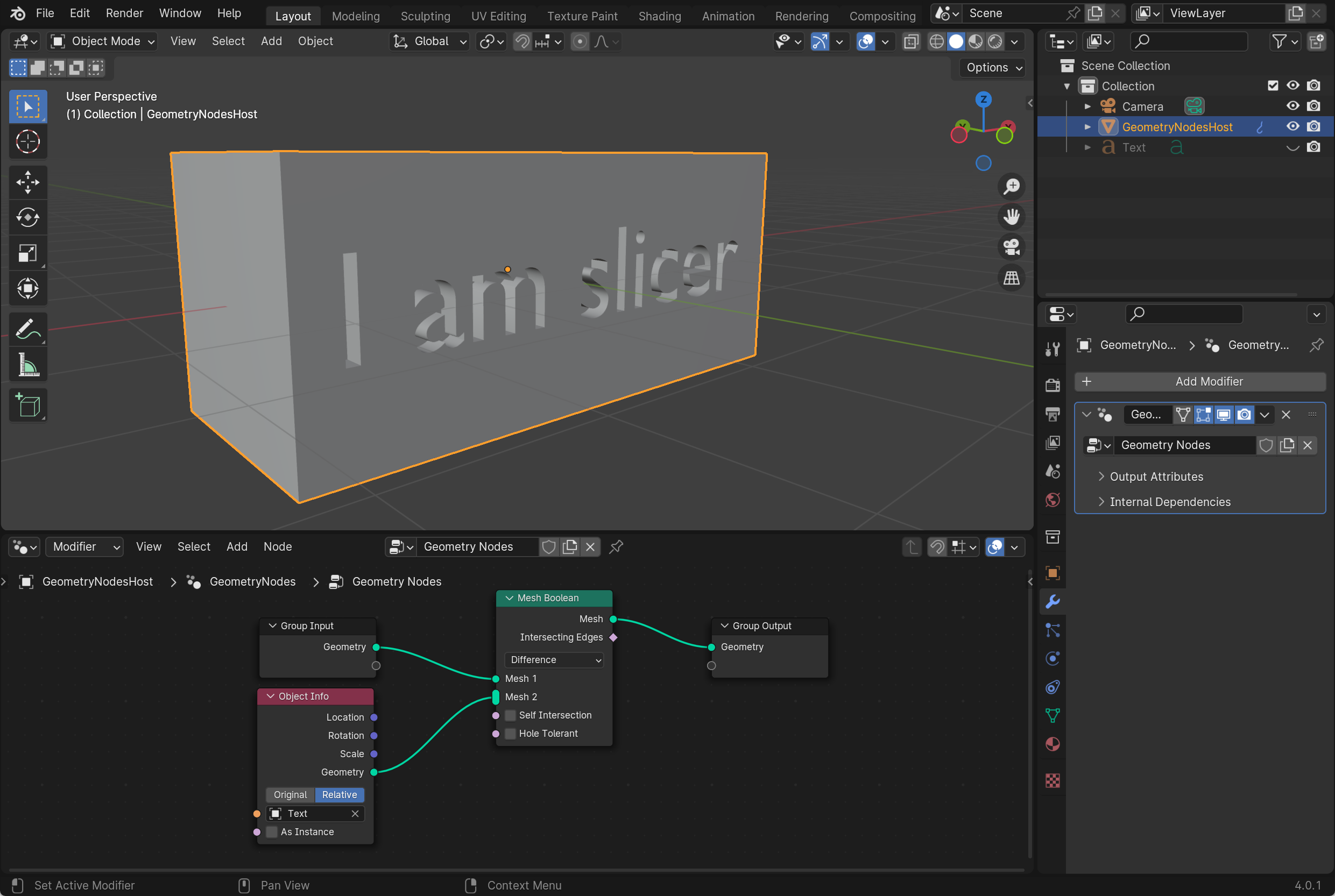
With the mesh Boolean node set to difference, this makes it so that all the mesh that is contained within the perimeter of the object referenced in the object info node is deleted. Keeping only the geometry outside of it.
If you look at the mesh Boolean mesh 2 input, you can see that it is elongated. This means that it can take several inputs, allowing us to cut away at mesh 1 using multiple inputs in mesh 2, like this.

However, using multiple inputs in mesh 2 can sometimes lead to calculation errors, leaving us with a mesh we didn't intend. In those cases, we can serialize the calculations, using a mesh boolean for each object like this.

This kind of setup usually leads to a more predictable result.
For the settings on the mesh boolean, self intersection and hole tolerant, I have found that they can sometimes help as corrective measures if one of the intersecting meshes is non-manifold. Either by intersecting itself or if it contains holes. According to the Blender manual, both add significant calculation time, so for larger or bulk operations, use with caution or only when necessary.
The intersecting edges output is a selection of all the edges at the point of contact between the two objects. You can use this output to isolate other operations in your node graph.
Previously, we briefly touched on what the different boolean operations we can perform are. So far, we also only used the difference type while demonstrating the mesh boolean node. Here we will show how each of the operations looks in geometry nodes. Then we will take a further look at how we can combine booleans to create our own slicing modifier.
In these examples, we use a text object in the object info node so that we can clearly see the difference between the two objects used.
The difference is the only type that uses two mesh inputs. The objects input in mesh 2 will cut away at the object we input in mesh 1. So if you don't get the result you expect, try switching them around.
Union only has one mesh input- It takes all the meshes connected to this input and merges them together. Just like with all mesh inputs, we can use the mesh from the object we attach the geometry nodes to, a second object through the object info node or any primitive we can add through the mesh primitive nodes.

Here you can see in the outliner that the text object is hidden, but its geometry has now become part of our cube in a union operation. The vertices where the two objects meet have been merged.
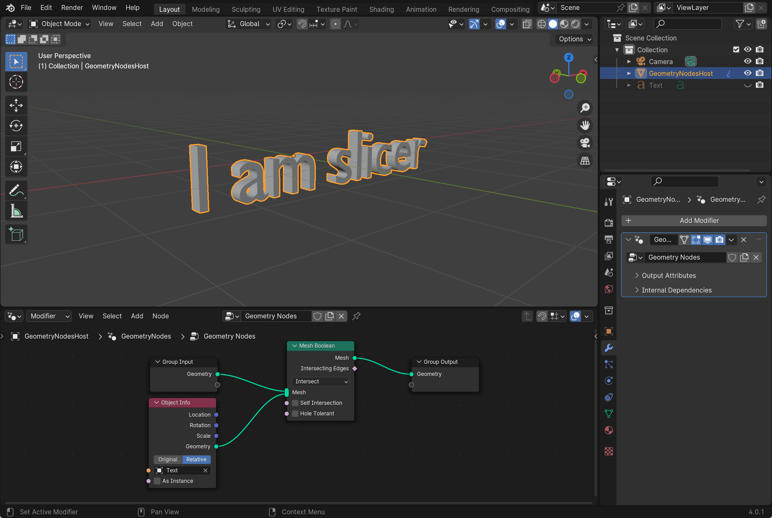
In this example, we only see the text in half its thickness. The half that is dug into the cube is left since this is the part of the two objects that intersect.
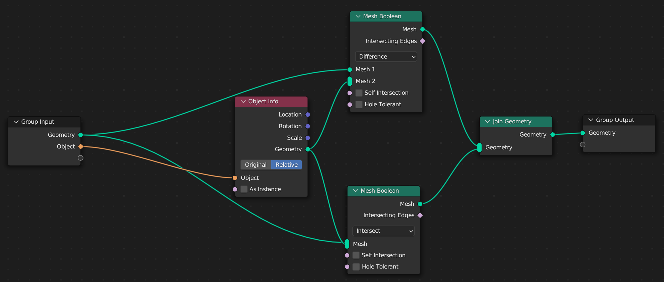
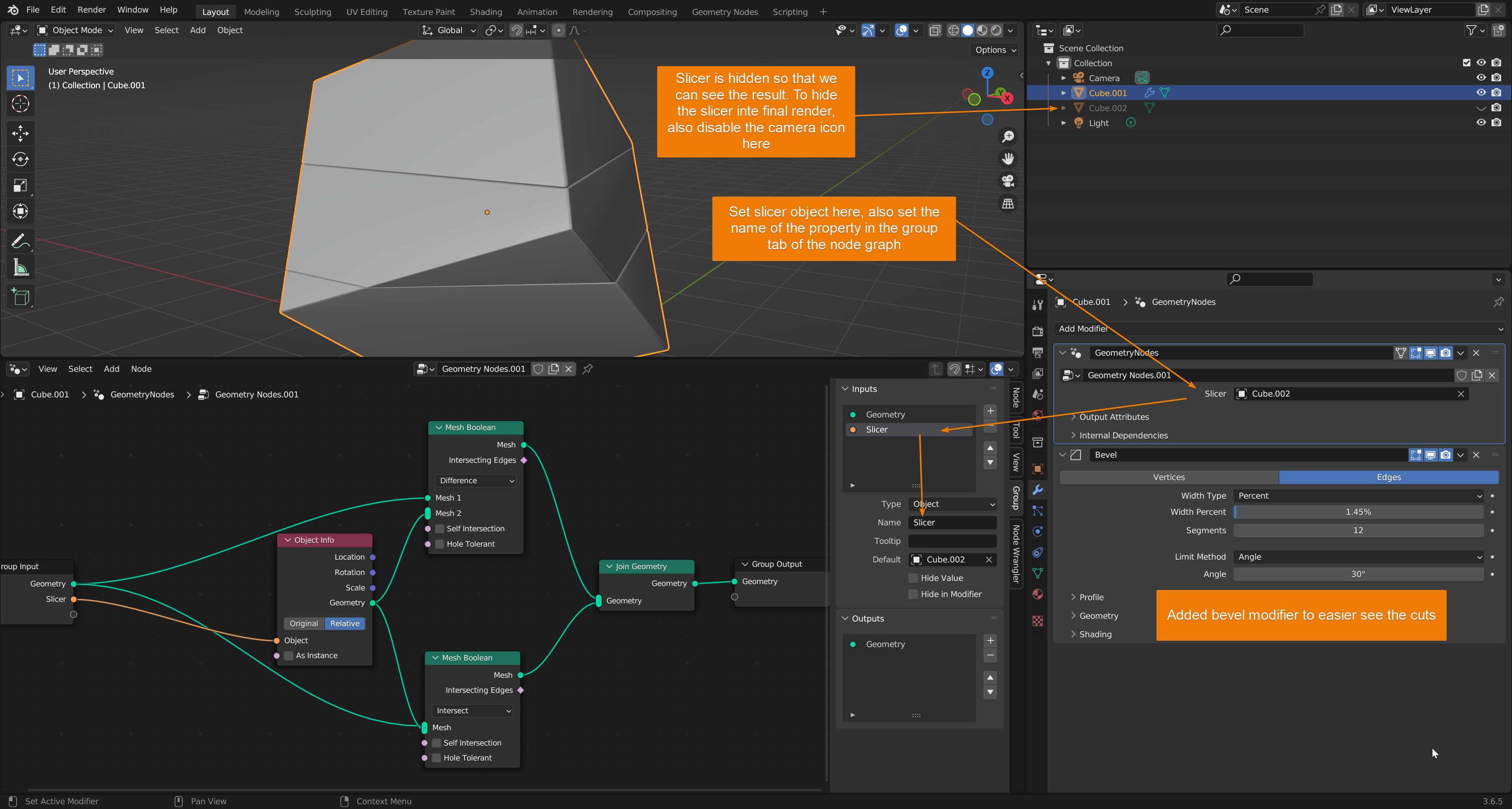
A slice is a combination of a difference and intersect operation. Here is the node setup.
Let's start by discussing limitations. With this setup, we cannot slice with a plane or another non-manifold object. It works best if we have one object we want to slice into and then another object with the slice shape on one end and is closed in the other.
For example, if you want to cut a plane through a cube, don't use a plane, instead use a cube scaled up and slice through your object using just one side of the cube like this.
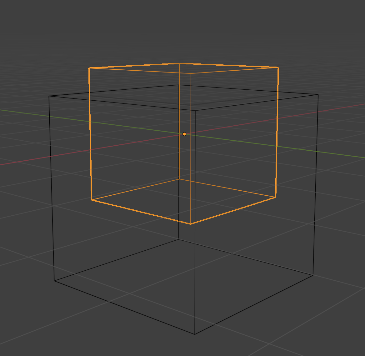
This will slice a clean cut with the upper face through the smaller cube.
The node group takes our object and performs a difference operation, keeping the part of our object that isn't within the bounds of the slicing object. Then it performs an intersecting operation, keeping the portion of our object that is within the perimeter of the slicing object.
We then join the now two separate pieces and output the result.
To use the slicer modifier, we simply add it to our objects modifier stack, choose a slicer object in the modifier interface and since the object property is exposed in the modifier through the group input node, we can pick a slicer object from our scene with no node graph.
For an extensive guide on how to troubleshoot boolean operations that don't behave the way you want, you can check out this guide on fixing boolean modifier problems. However, most problems we had in the past were because of the fast solver rather than the exact solver that the mesh boolean node is based on.
Related content: Boolean modifier problems and how to solve them
In most cases when we don't get what we want in a boolean operation, we may need to make sure that we are using the correct operation and in the case of a difference operation, make sure that we have the correct mesh in the correct input slot.
For most use cases, we also want to hide the object we used to remove or add to from the other object. If we don't, the objects may intersect or there may be an object where there should not be one.
Don't forget to hide the object for both the viewport and the final render so that there are no surprises when you hit F12.
If the mesh is not behaving at all as you expect. You might see weird edges or just part of one object remain while others have disappeared, or one object might have become a blob hovering around the edges of the other object, try just slightly move the object so that the vertex positions are updated and you may get the result you are looking for.
This problem is very common with the fast solver on the boolean modifier, but sometimes still appears when using the exact solver as well.
The boolean mesh node is a powerful tool and combined with all the other tools Blenders geometry nodes offers, it is a powerful part in a larger system.
We looked at the different operators essential to booelan operators. We discussed the difference between mesh boolean and the boolean as a data type in geometry nodes.
We also looked at an example where we created a simple slice modifier with geometry nodes by combining different boolean operations.
At the end, we also discussed some troubleshooting. Check your node connections and if you have the correct operation set. Also, don't forget to try to slightly move your object if it behaves unexpectedly.
Thanks for your time.
