


Geometry nodes are a great way to scatter objects but we need to know which nodes to use and how to connect them first. So how do we do it?
To scatter objects with geometry nodes:
In the rest of this article we'll go into more detail about the node setup with examples as well as some more options for customization.
Related content: How to use a particle system in Blender to scatter objects
Before we can start adjusting our scattered objects we will need to create points that our objects can be instanced onto. Go to Add -> Search -> Distribute Points on Faces. Connect the Geometry input to the Distribute Points on Faces Mesh input.
You can also press Shift+A while hovering the mouse in the geometry node editor to access the add menu.
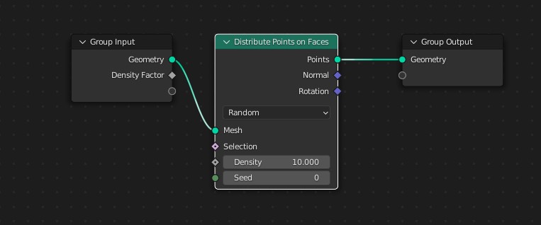
We can use the density value to adjust how dense we want our scattered objects to be. Adjusting the seed will randomize the placement.
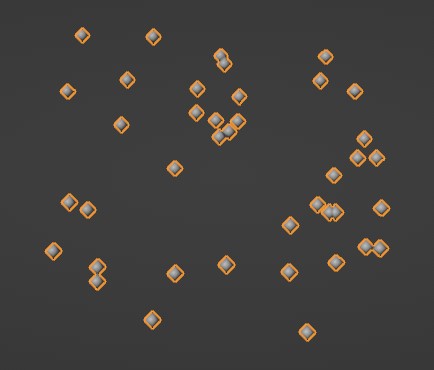
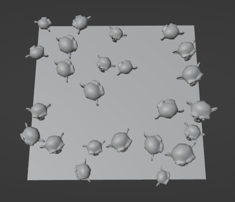
In the example below you can see how the mesh has been replaced with randomly scattered dots. THese are placed on the surface, or faces of our mesh as the distribute points on faces node suggest.
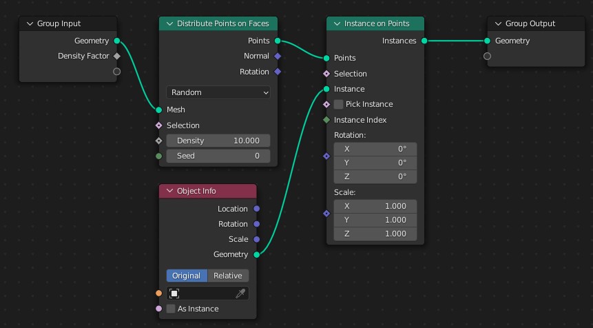
To actually get our objects to appear at these points we will need to instance them. Instancing is when we take an object or collection of objects and reference it multiple times. In this case, once for every point in our setup.
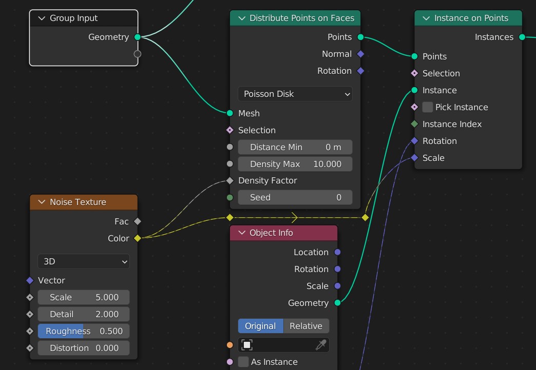
Go to Add -> Search -> Instances on Points and connect the Distribute Points on Faces Points output to the Point input of the Instance on Points node.

To get our Object into the geometry nodes we will need to use a Object Info node. Go to Add > Search > Object Info. Connect the Object Info Geometry output to the Instance Points Instance Input.
Now we can drag the Object from the scene or outliner into the input on our Object Info node. We can also type into the Object input to find any object in our scene.
Alternatively, we can go to the outliner directly and find the object we want to instance on our points and drag-and-drop it in our node graph. This will automatically create an object info node with that object populating the object slot.
The object info node gives us a few options, for example we can use a collection and we can also set our objects as instances which will help save on performance by making the scattered objects act as clones rather than unique objects. Connect the object info geometry output to the instance input of the instance on point node.
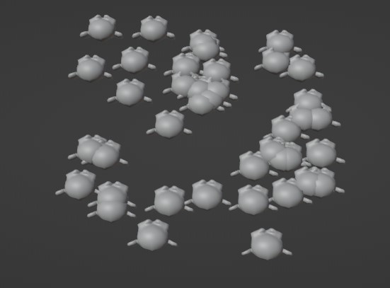
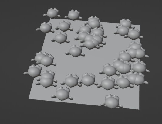
For demonstration purposes I choose the use the monkey mesh as the instance object, and this is the result so far.
Let's now look at how we can control the rotation and scale using values or textures. Then we will see how we can get our original mesh to be visible alongside our distributed instances.
We can adjust the rotation and scale of all instances at once by changing the rotation and scale values for each axis on the instance on points node.
But most often we also want to introduce some randomness to these values so that all instances don't get the same rotation and scale.
Let's start with the rotation.
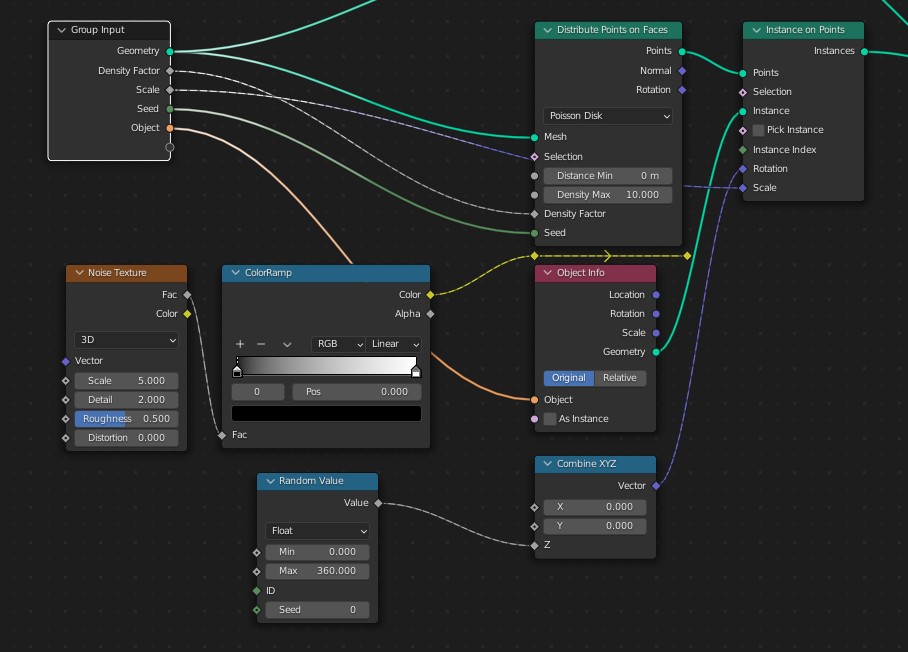
To randomize our rotation we will be adjusting the instance rotation value. For this guide we will use a combine XYZ and a random value node.
Create a Combine XYZ node and connect it's vector output to the Instance on Points Rotation vector input. Create a Random Value node and connect it's Value output to the whichever axis we're randomizing.
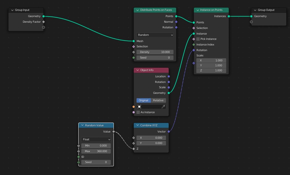
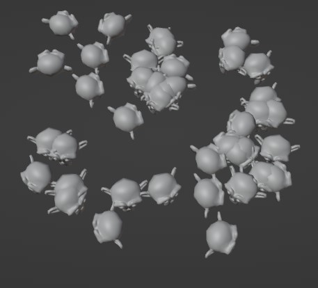
We can now randomize the rotation of our scatter by either setting the random value limit to 360 or whatever limit we may want. We can also adjust the seed to get different a different randomness pattern.
Randomizing the scale is similar. You may notice that the Scale input is a vector as well, but rotations and scale vectors are different, just like color values are different from vectors. But we can still use them in similar ways.
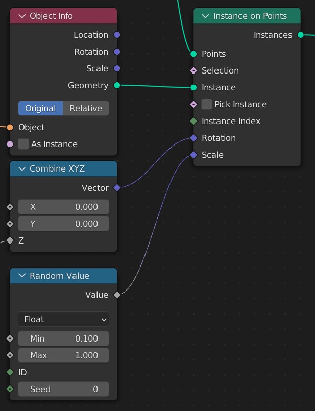
We can just plug the value directly into the Vector and Blender will usually do the rest but in case this doesn't work or we want to adjust the X Y and Z values independently we can use a Combine XYZ node to combine each value into a vector that we can use for the scale.

We can use textures to control many values in our geometry node graph. We can either use a image texture or the many noise types that Blender comes with.
Let's see how we can setup our instances so that they get scaled and distributed depending on a noise textures pattern.
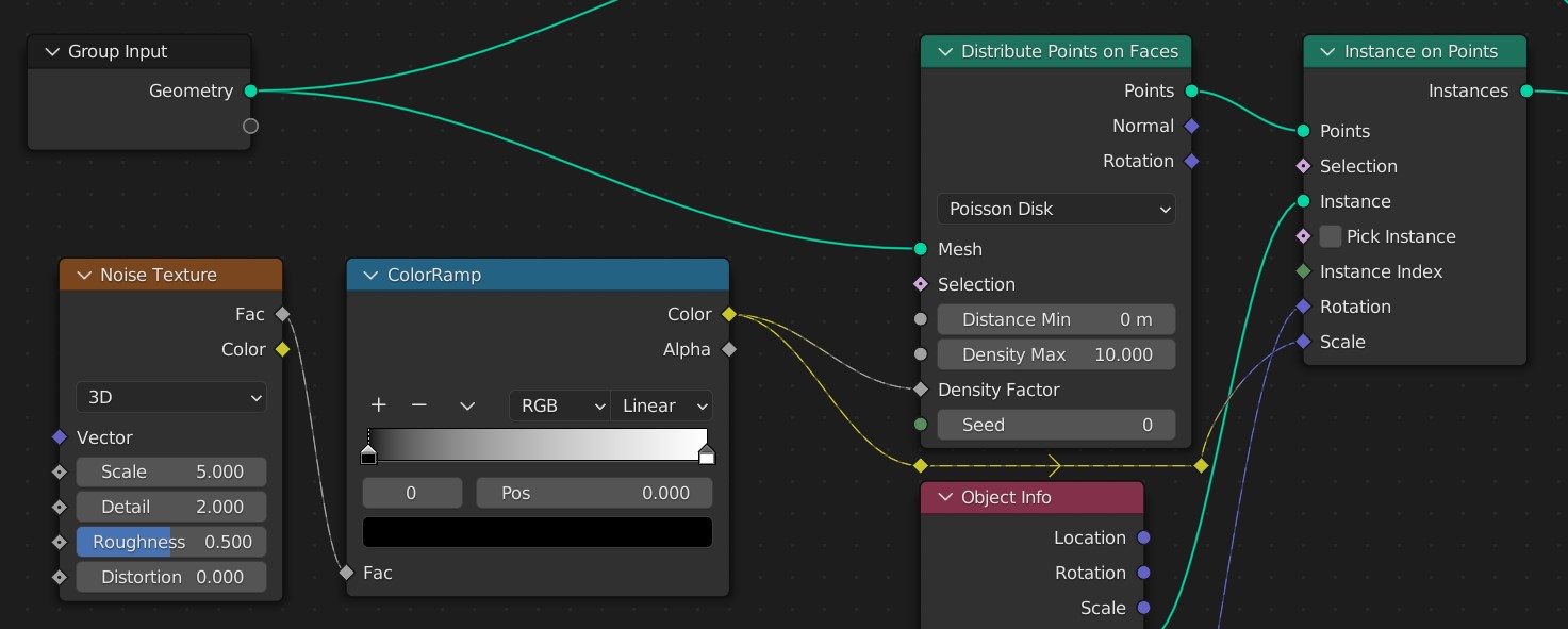
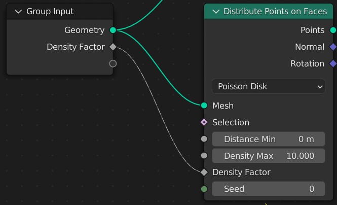
Go to Add -> Texture and select the noise texture. With the texture node added, change the distribution method of the distribute points on faces node from random to poisson disk.
We can now connect the noise texture color output to the density factor.
If you prefer, you can stick to the random distribution and use the density factor input. But later we will use poisson disk to stop some of the clipping from happening between our instances.
We can also directly plug the texture into the scale vector if we are using the same value for each axis.
If we want more control, we can also feed the noise texture output to a color ramp node before we plug it in to either the density factor or the scale vector input.
Related content: How the color ramp node works in Blender
Adjusting the scale of each axis individually can be done by using a combine XYZ node and connecting its output to the scale. We can then input a separate value for each axis.
You may notice that currently we cannot see the original object, this is because we need to recombine the objects we've create with the original object. We can use a join geometry node and connect the original object with the output from the instance on points node before connecting the join geometry node to the group output.
Go to Add > Search > Join Geometry. Connect the Group input to the join Geometry Input then connect the Instance to Points Instances output to the Join Geometry Input.

The Join Geometry Input is a bit different then many of the node inputs as you may notice, it allows us to connect multiple objects to the same input. The data will simply be joined together in this node to be fed forward in our node tree.
To stop clipping we can use the poisson disk distribution method like we did earlier to get access to the density factor. On the Distribute Points on Faces node we can click on the drop down for the distribution method and set it to Poisson Disk.
With the Poisson Disk distribution method instead of just having a density value we can set the minimum distance between points.
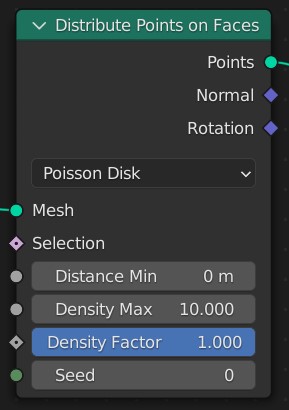
For this example I've increased the Distance Min until I don't see any more objects clipping and then I can use the Density factor to control when the points are and use Density Max to control how dense the points actually are.
We can also use vertex groups to distribute our instances on the mesh. A vertex group is considered external data from the geometry node trees perspective. Therefore we have to get it into the node graph and make it available first.
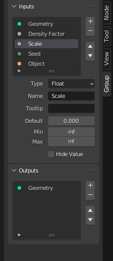
Start by connecting the factor we want to control to the Group Input node. In this case, use the density factor from the distribute points on faces node. Note that we kind of connect it backwards. When we connect to one of the dark grey sockets it will create a new input we can control.
To access the group input and output nodes sockets, you can press N to open the properties panel and go to the group tab. Next expand the inputs or outputs section to change any parameter for the group node sockets.
Related content: How to use vertex groups in Blender
Once we have connected the density factor we can input data into it from the modifier tab. But first we need some data to connect.
Go to the object data tab represented by a green triangle icon in the properties panel and expand the vertex group section. Press the plus sign and if you want, rename the group.
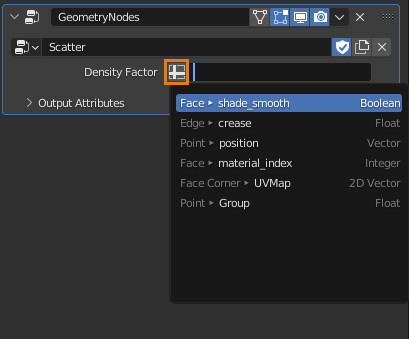
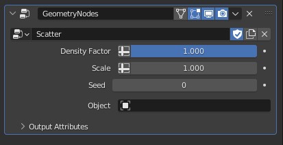
Next go to the modifier tab and you will see that we have a density factor slot. This is because we created the extra slot in the group input node. Here we can attach data that we can then access in the geometry nodes tree.
Click the plus sign icon on the left side of the input field and find your vertex group by name and select it.
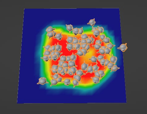
We can now go into weight paint mode and paint where we want our objects to be scattered.
By plugging in another slot, like the scale from the instance on points node and assigning that to a vertex group in the modifier stack we can use vertex groups to influence many kinds of data in geometry nodes.
Related content: Top 10 weight paint tips for Blender
Any node that has input sockets can be connected to the Group Inputs node, this will allow us to assign the inputs from the geometry node modifiers.
This will also be per object instead of affecting all of the modifiers. Any effects that are supposed to apply to all of the modifiers should be assigned in the modifier.
When we connect any value to the Group Input node it will create a input for that value. We can also adjust each of these input by opening the property panel with the N key and selecting the input we want to configure.
Adding our inputs this way allows us to modify the geometry node modifier properties without having to adjust it inside of the graph and like mentioned earlier will be unique to that object.
Geometry nodes can be a very useful and customizable option for scatter objects. Unlike Particle Systems which aren't necessarily designed for scatter objects Geometry nodes give us much many more options and allow us to achieve a wide variety of effects.
Thanks for your time.
